anyone know of a module that would quantize a gate to the next quarter, half or whole note?
so you send a gate on into it and it waits until the next beat or specified time division to spit out the gate on. you turn off the gate and it waits until the next beat to spit out the off.
cant seem to find any module that fits the bill for this idea exploring. tia!
Maybe this will work, perhaps with a clock divider?
This is not in the MM library yet, but:
I am still learning this stuff and posts like this help me with understanding. I know this is a delay but the form of words used seem similar and I am thinking the Trig and Pre may get you some way there. KRT “L” describes itself as this if of any use " A synchronized delay with a PRE control to remove a time dependant on sample latency so as to match timing one synchronization trigger later. So suppose you wish to synchronize to some live play and are prepared to time up one TRIG later (say a bar for arguments sake), then you can increase PRE to achieve that less than the bar delay with latency compensating the rest of the bar delay which PRE removed on OUT . The output PRE gates high before the bar end to allow down module to trigger other things with the need to be triggered before the bar start."
you could create with basic modules.
use a logic module , then AND with a clock (divider) - treat this as a trig, then use a trig->gate module.
i.e
gate, clk/n → and → (trig) trig2gate.
ofc, you can skip the trig2gate, if you only need a trig, e.g. for AD envs or alike.
this would have a slight issue if you had two gates within a quantised period, (it’d coerce into one)
practically, shouldn’t really be an issue, and would likely be an edge case for a dedicated module.
for sure, a dedicated module would be simpler, but I enjoy thinking how to build from basic building blocks 
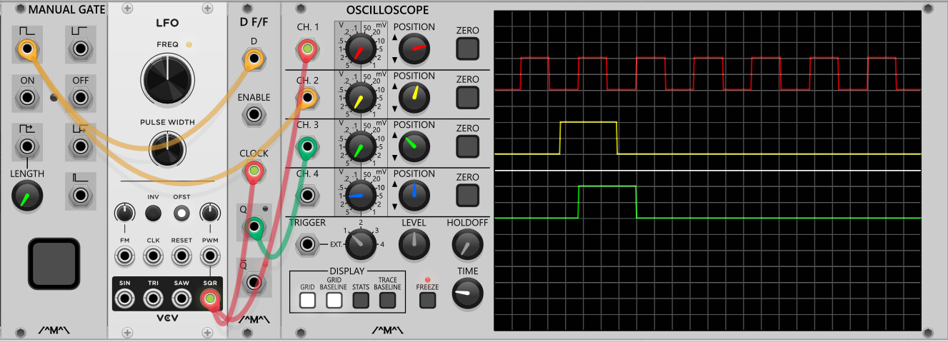
D type flip flop.
Gate into the D input then use whatever you want to quantise to as the clock.
If the D input is high when the clock goes high, the Q output will go high, if the D input is low when the clock goes high the output will go low.
2 Likes
Red trace is the clock coming from the LFO
Yellow trace is the gate coming from the manual gate module
Green trace is the manual gate quantised to the LFO clock.
Note that if the gate goes high and low again in between clock pulse it will not register.
3 Likes
thanks all for the help!
excellent ty! looks like this will do just the trick.
1 Like