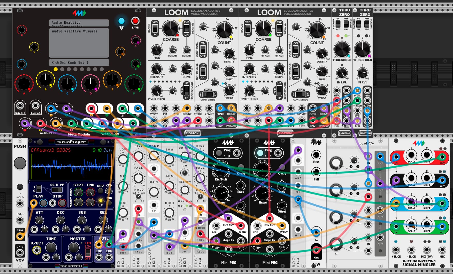
This patch takes incoming audio and generates CV for use with a vector monitor to generate audio reactive visuals.
YouTube video of Audio Reactive Oscillographics
External Audio Path:
-Main audio outputs on channels 3 and 4
External CV Path:
-CV “X” output on channel 1
-CV “Y” output on channel 2
-CV “Z” output on channel 3
-Audio based envelope followers for audio left and right on channels 7 and 8
Internal Audio Path:
-Audio lfed into a 3 band EQ to filter out desired frequencies (left channel = bass, right channel = highs)
-The 3 band EQs are fed into an envelope follower, a VCA, and a SISM for level shifting
-Two additive oscillators are fed into thru zero VCAs and then to each X and Y output respectively. The Thru Zero amplitude allows for images to be modulated in all 4 vectors of the screen.
Internal CV Path:
-The filtered audio is fed into a comparator.
-The comparator triggers a 5v envelope
Metamodule Knob Mappings:
A - Oscillator A frequency
B - Oscillator A partial count
C - Oscillator A Stride
D - Oscillator B thru zero VCA offset
E - Oscillator B partial count
F - Oscillator B frequency
X - “Z” attenuator
Y - High frequency audio envelope attenuator
Z - Low frequency audio envelope offset
Audio Reactive Oscillographics.vcv (3.8 KB)
Audio Reactive Oscillographics.yml (15.6 KB)